
How to Install an Outboard Motor Correctly
An outboard motor installation requires accuracy. If done improperly, it can harm your boat or pose major threats to your safety while out on the sea. The official Suzuki procedures for installing an outboard, setting up controls, and choosing the appropriate battery and propeller are described in this document. This blog will cover install for both tiller and remote models. If you are unsure or inexperienced have an authorized professional install your motor.
Here are Suzuki's official instructions on how to properly mount an outboard motor, which should be known by all boaters.
🛑 Respect Horsepower Limits
Any marine dealer that installs or services a motor that is more powerful than the maximum horsepower rating indicated on your boat's certification plate is breaking federal law.
- Locate the plate on the hull of your boat, usually close to the transom or helm.
- Overpowered boats are dangerous and can result in insurance cancellation, therefore never go over this rating.
- Underpowered rig may struggle to perform adequately, leading to poor handling, sluggish acceleration, and inefficient fuel consumption.
- Match the application (e.g., fishing, water sports, or leisure cruising) to identify the ideal horsepower that balances power and efficiency.
⚙️Establish the Proper Transom Height
Optimal performance is ensured by the proper transom height, using the guides below to help:
- The propeller may slip and the engine may overheat if the motor is set too high.
- It lowers speed and produces drag if it is set too low.
Target position: When the motor is fully lowered, the anti-cavitation plate should be positioned between 0 and 25 mm (0 and 1 in.) below the bottom of the hull.
🔧 Safely Mounting the Motor
Below are templates for your specific motor:
- Carefully position the motor on the center of the transom.
- By hand, uniformly tighten the clamp bracket screws
- Ensure that the anti-cavitation plate is positioned between 0 and 25 mm (0 and 1 in.) below the hull's bottom.
- From inside the transom, drill through the clamp bracket holes.
- From the inside, install 8mm bolts, washers, and lock nuts after drilling mounting holes and applying marine sealant to stop water entry all of the bolt.
- Verify that the tilt and steering move easily after installation and that nothing is obstructing them, such as the battery cable.
⚠️ WARNING: Never rely on clamp screws alone, the motor can shake loose and come off.
Connecting the Shift Control Cable (Remote Models)
- Remove the starboard engine side cover
- Set the handle of the remote control to NEUTRAL.
- Take off the clutch control lever's washer and lock pin.
- Align the cable's groove with the holder slot to route the shift cable through it.
- Verify that the clutch control lever is in the neutral position.
- Thread the connector onto the shift cable while pressing the cable end until the clutch lever's pivot pin and the connector's hole line up.
- With the flat side facing the lever, attach the connector to the pivot pin.
- Important: To avoid breaking, thread the connector into the cable at least 8 mm (0.3 in.).
- Tighten the lock nut after reinstalling the washer and lock pin.
- Verify that the remote handle travel from neutral is equal for the forward and backward gears.

Connecting the Throttle Control Cable & Remote Control Harness (Remote Models)
- Remove the lock pin and washer from the throttle lever
- Set the handle of the remote control to NEUTRAL.
- Slide the throttle cable into the designated holder.
- Verify that the throttle drum is closed all the way.
- To achieve clearance "a," turn the throttle control lever counterclockwise.

- Attach the throttle cable connection by threading it onto the end of the cable.
- Adjust the connector until the connector hole lines up with the throttle lever's pivot pin while pushing the cable end.
- Attach the connector (flat side facing the lever) to the pivot pin.
- Tighten the lock nut after reinstalling the washer and lock pin.
- At maximum throttle, make sure the throttle stopper makes contact with the stopper block. If necessary, make another adjustment.
- Put the remote control back in NEUTRAL and confirm:
- The throttle drum is closed completely.
- Make sure there is a gap between the link lever and the interlink lever.
- Before installing side cover, confirm that the remote control harness and PTT motor cable are properly routed and they must not contact with the remote control cable holder.
- If the harness touches with the cable holder, pull the harness outward at its grommet.
- Replace the engine side covers.
- Attach the engine-side coupler to the remote control wire harness coupler.
- On the T model; Do not connect the sub-battery cable to the remote
control harness. For this model, it is not necessary to connect the sub-battery cable to provide power for operation of the engine control system. If you connect the sub-battery cable, the sub-battery fuse will blow.
Installing Steering
NOTE: The steering cable must be installed before the outboard motor is installed on the majority of outboard motor installations.
These instructions are for connecting a mechanical push-pull
steering system with the following specifications:
- Single cable
- Starboard cable entry into the motor tilt tube.
- Steering cable meeting the current American Boat and Yacht
Council’s Safety standard (P-17).

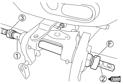
- Attach the steering cable seal F to the motor tilt tube 1's port side end.
- Lubricate the second steering cable with SUZUKI WATER RESISTANT GREASE.
- Tighten the cable holding nut 3 to the torque recommended by the cable manufacturer after inserting cable 2 into tube 1 from the starboard side.
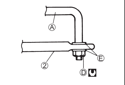
- Using washers E and safety nut D as shown, attach drag link A to steering cable end
- After achieving the required torque on nut D, back the nut off 1/8 TRN.
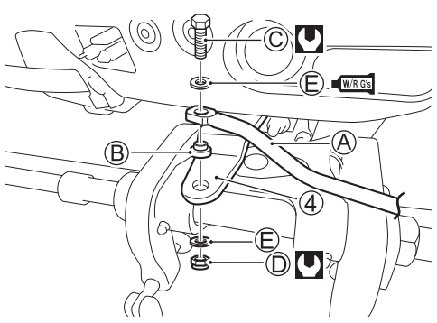
- Adjust the steering cable until attachment 4's thread hole and drag link A's hole line up.
- Attach attachment 4 to the drag link by tightening the bolt C as shown, using washer E and spacer B.
- Secure safety nut D.
⚡ How to Pick and Set Up the Correct Outboard Battery and Propeller
For your outboard to operate as efficiently and dependably as possible, selecting the appropriate battery and propeller is essential. Here's the proper way to do things.
🔋 Models with Electric Start Need Batteries
For dependable starting and powering electronics, your outboard requires a robust 12-volt cranking-type lead acid battery.
Minimum scores:
- ABYC / 450 Marine Cranking Amps (MCA)
- or 330 SAE (Cold Cranking Amps)
- or 70 Minutes of Reserve Capacity (RC) / SAE
Important advice:
- If your boat has additional electronics, strive for a higher grade; these are the minimums.
- If dual-purpose (deep-cycle/cranking) batteries fit the aforementioned specifications, they are acceptable.
- Deep-cycle batteries don't provide enough burst power, therefore don't utilize them as your primary starting battery.
- Steer clear of sealed, maintenance-free, or gel-cell batteries since they could not be compatible with Suzuki's charging system.
- Batteries must have the same type, brand, capacity, and age if they are wired in parallel. They should also always be replaced as a set.
Basics of Battery Installation:
- Place the battery in a dry, vibration-resistant location.
- To avoid corrosion and spillage, use a sealed battery box.
- For a secure, tight fit, use hex nuts on battery posts rather than wing nuts.
- When establishing a connection:
- Prior to connecting black (negative), connect red (positive).
When unplugging:
- Disconnect red (positive) after black (negative).
- Sparks and unintentional short circuits are less likely to occur with this sequence
Selecting the Appropriate Propeller:
- Fuel efficiency, top speed, and engine RPM are all directly controlled by your propeller.
An incorrect pitch might harm the motor or impair performance.
Generally speaking:
- More RPM and torque are produced by smaller pitch props (for high loads or towing).
- For lesser loads, larger pitch props result in lower RPM and higher top-end speed.
Target WOT RPM ranges for these models:
- DF9.9B → 4700-5700 rpm
- DF15A → 5000-6000 rpm
- DF20A → 5300-6300 rpm
You need extra pitch if your engine is overrevving.
Less pitch is required if it's under-revving.
Expert Advice:
- Always use a tachometer to test under typical load conditions.
- Every time you switch props, check the RPM again.
- A prop can be sized for your setup by your authorized Suzuki Marine Dealer.
✅ After Installation Checklist
- Plate to prevent cavitation 0–25 mm below the bottom of the hull
- All bolts were tightened and sealed
- Tilt and steering are free to move
- Cables that are securely fastened, linked, and routed
- The battery is properly wired and placed in a dry, stable box
- The WOT RPM was within range when the propeller was tested under load.
Do you require expert setup or installation? BoatMaxOnline provides complete Suzuki-certified outboard setup, rigging, and installation, including propeller sizes and battery systems.