How to Set up your New Outboard Motor

When selecting and installing an outboard motor, choosing the right horsepower is critical to both safety and performance. Here’s a practical breakdown based on your notes:


Key Considerations for Horsepower Selection

1. Maximum Horsepower Limit

  • Determine the Boat's Capacity:
    Each boat has a manufacturer-recommended maximum horsepower capacity, typically displayed on a capacity plate. This is a critical guideline to ensure safety and compliance.
  • Product Liability:
    Exceeding the maximum horsepower capacity poses a severe liability risk, as it compromises safety and may result in accidents or legal issues.

2. Avoid Underpowering

  • Performance Balance:
    An underpowered rig may struggle to perform adequately, leading to poor handling, sluggish acceleration, and inefficient fuel consumption.
  • Match the Application:
    Discuss the customer's primary use of the boat (e.g., fishing, water sports, or leisure cruising) to identify the ideal horsepower that balances power and efficiency.

Dimensions and Drill Hole Template

DF2.5 Dimensions and Clamp Bracket Template

We have the Suzuki DF2.5 Dimensions and drill hole templates available for your convenience.

Suzuki DF2.5 Dimensions and Clamp Bracket Templates

DF4A/6A Dimensions and Clamp Bracket Templates

We have the Suzuki DF4A/6A Dimensions and drill hole templates available

Suzuki DF4A/6A Dimensions and Clamp Bracket Templates

DF9.9B/15A/20A Dimensions/ Templates

We have all the Suzuki 9.9B/15A/20A Dimensions and drill hole templates available for the different models.

Suzuki DF9.9B/15A/20A Dimensions and Drill Hole Templates

DF25A/30A Dimensions/Templates

We have all the Suzuki 25A/30A Dimensions and drill hole templates available for the different models.

Suzuki 25A/30A Dimensions and Drill Hole Templates

Honda BF2.3DH Dimensions

We have the Honda BF2.3DH Dimensions and drill hole templates available

Honda BF2.3DH Dimensions

Honda BF5D Dimensions

We have the Honda BF5D Dimensions and drill hole templates available

Honda BF5D Dimensions

Honda BF8D/BF9.9D Dimensions/Templates

We have the Honda BF8D/BF9.9D Dimensions and drill hole templates available

Honda BF8D/9.9D Dimensions and Drill hole Templates

Honda BF15D/BF20D Dimensions/Templates

We have the Honda BF15D/BF20D Dimensions and drill hole templates available

Honda BF15D/20D Dimensions and Drill Hole Templates

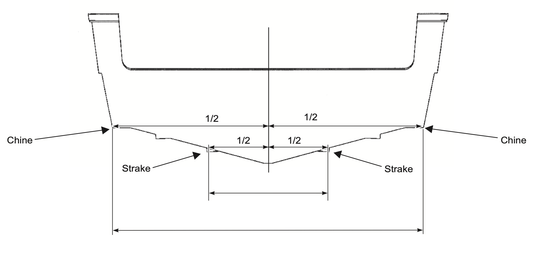
Establishing the Center-Line

Establishing the Center-Line

Mark the Transom Face:

  • From Chine to Chine: Measure across the transom from chine to chine. Mark the halfway point
  • From Strake to Strake: Measure across the transom from strake to strake. Mark the halfway point.

Draw the Center-Line:

Align a straightedge with the two marks and draw a vertical line. This is the center-line of the transom for a single-engine installation.

Lifting the Motor

Important Notes:

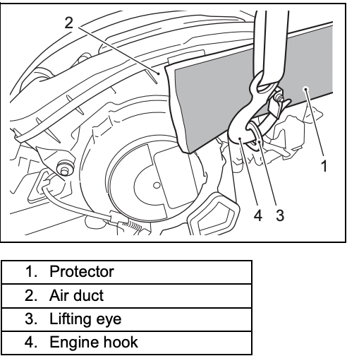
  • Always lift the motor using the lifting eye on the cylinder block.
  • Use a hoist with a minimum lift capacity of 450 kg (1000 lbs.).
  • Protect the air duct from damage by using a protector between the engine hook and the air duct.

Steps to Lift the Motor:

  1. Attach the hoist to the lifting eye.
  2. Lift the motor carefully.
  3. Avoid using a flywheel lifting attachment.

Mounting the Motor to the Transom

Position the Motor:

  • Center the motor on the transom.
  • Ensure the anti-cavitation plate is 0–25 mm (0–1 inch) below the boat bottom.

Secure the Motor:

  • Tighten clamp screws alternately by hand.
  • Install mounting bolts with large flat washers 
  • Use proper reinforcement plates if needed for weak transoms.

Tighten Bolts and Nuts:

  • Install flat washers and nuts (look into owner's manual for proper mounting)

Notes:

  • Seal all bolt holes with a water-tight sealant (e.g., Suzuki Silicone Seal).
  • Do not use an impact tool for tightening or loosening.
  • Retighten bolts/nuts after the break-in operation (10 hours).
  • Ensure no clearance exists between the clamp bracket and the transom surface.
  • Use spacers if needed to support the motor's weight.
  • Avoid using impact tools for mounting and dismounting.

Routing of Control Harness

Remove the STBD Engine Side Cover:

Detach the starboard (STBD) engine side cover to access internal components.

Route the Remote Control Harness:

Pass the remote control harness through the grommet

Connect the Harness:

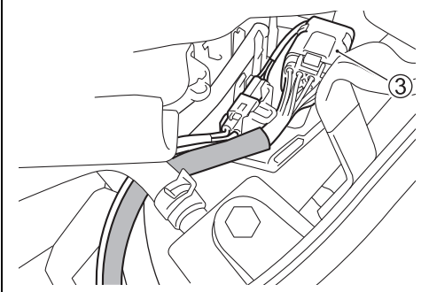
Attach the remote control harness to the engine side.

Press-fit the connector (3) into the connector holder.

Installation of Control Cable

(1) Remove the STBD engine side cover.

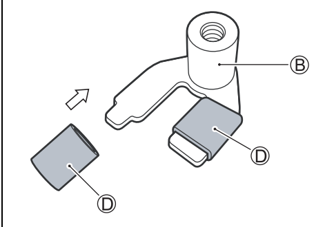
(2) Install the cable cushions D to cable stopper B.

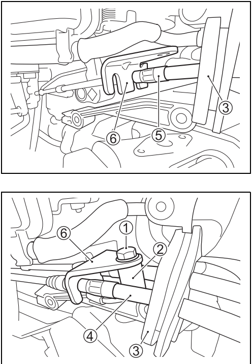
(3) Install the throttle control cable 4 and clutch control cable 5 through the grommet 3 as shown in figure.

(4) Secure the cable 4 and 5 in the cable holder 6 by fitting groove on the cable into a slot on the holder as shown figure.

(5) Install the cable stopper 2 using the bolt 1 to secure the clutch control cable and throttle control cable.

(6) Position the remote control handle into “NEUTRAL”

Shift control cable Installation

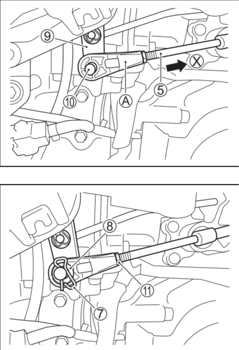
(7) Remove the lock pin 7 and washer 8 from clutch control
lever.
(8) Make sure that clutch control lever 9 is in the neutral position.
(9) While pushing cable end as shown by arrow X, thread the
connector A onto the shift control cable 5 until the connector hole aligns with the pivot pin 0 on the clutch control
lever 9.
(10) Set the connector A onto the pivot pin 0 with the flat side
of connector towards the lever.
(11) Install the washer 8 and lock pin 7, then tighten the lock
nut A.
(12) Make sure that both forward and reverse gear can be
engaged with the same angle of remote control handle
travel from “NEUTRAL” position.

Throttle control cable Installation

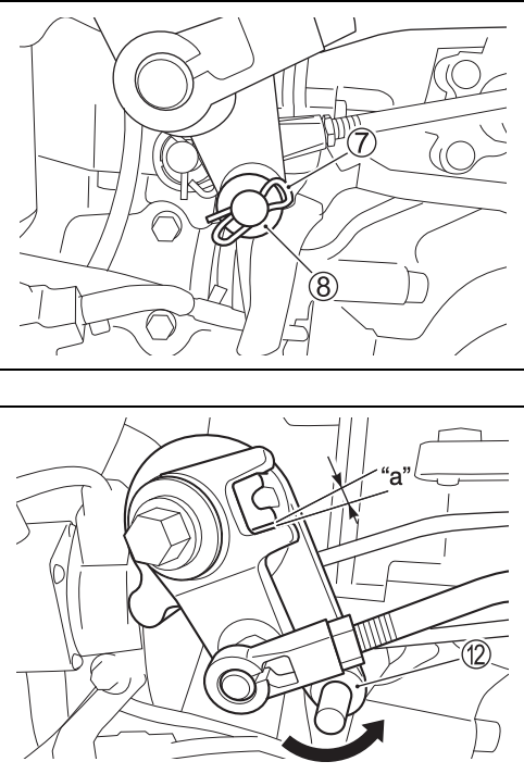
(13) Remove the lock pin 7 and washer 8 from throttle control
lever.

(14) Position the remote control handle into “NEUTRAL”.

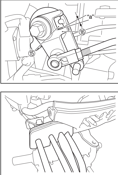
(15) Check that throttle is fully closed position.

(16) Turn the throttle control lever B counterclockwise until the
clearance “a” exists.

Clearance “a” 1 – 2 mm

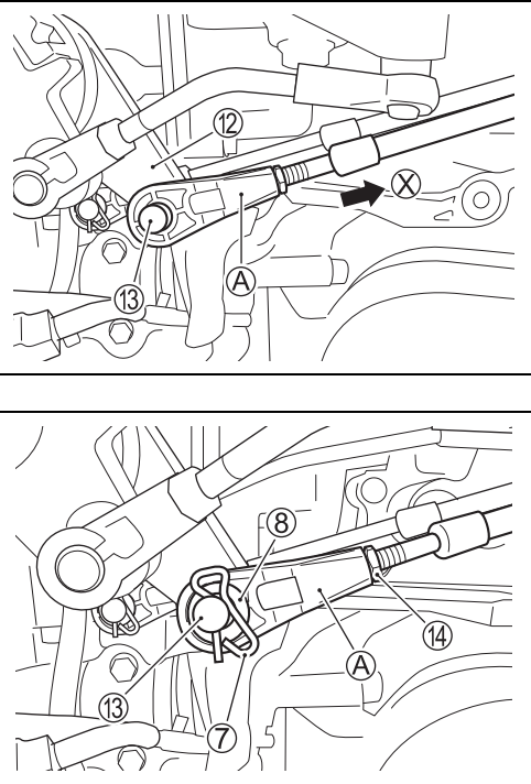
(17) Thread the throttle cable connector A onto the throttle cable end.

(18) While pushing cable end as shown by arrow X, adjust the connector A until the center of connector hole aligns with
the pivot pin C on the throttle control lever B.

(19) Set the connector A onto the pivot pin C with the flat side of connector towards the throttle control lever.

(20) Install the washer 8 and lock pin 7, then tighten the lock nut D.

(21) Move the remote control handle to fully opened position, then return the remote control handle to the neutral position.
Check that the throttle is in fully closed position.
Also make sure the clearance “a” exists between the interlink lever E and the link lever F with throttle control fully closed position.

Clearance “a” 1 – 2 mm

(22) Reinstall the engine side covers.

NOTE:
After assembly, make sure that the cables are not stretched or otherwise stressed when the outboard motor is turned all the way to the right and left.

Steering System Installation Procedure

Install the Steering Cable

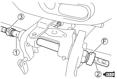
  1. Thread the steering cable seal F onto the port side end ofthe motor tilt tube 1.
  2. Apply SUZUKI WATER RESISTANT GREASE to the steering cable 2.
  3. Insert the cable 2 into the tube 1 from the starboard side, then tighten the cable retaining nut 3 to the torque specified by the cable manufacturer.
    NOTE:
    On most outboard motor installations, it will be necessary to
    install the steering cable prior to the outboard motor installation.

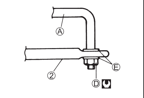
4. Connect the drag link A to the steering cable end 2 with washers E and safety nut D as shown. Tighten the nut D to the specified torque, then BACK THE NUT OFF 1/8 TURN.

Safety nut D: 10 N·m (1.0 kgf-m, 7.0 lb-ft)

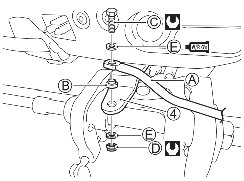
5. Move the steering cable until the hole of drag link A aligns with the thread hole on the attachment 4.
6. Connect the drag link to the attachment 4 by tightening the bolt C with the spacer B and washer E as shown.
Bolt C: 34 N·m (3.4 kgf-m, 24.5 lb-ft)
7. Install the washer E and nut D, then tighten the safety nut D.
Safety nut D: 34 N·m (3.4 kgf-m, 24.5 lb-ft)